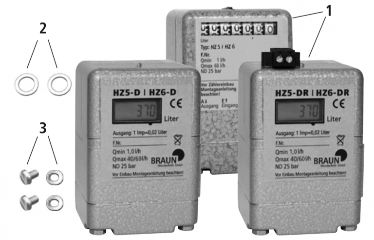
Scope of supply
1. Oil meter HZ 5/HZ 6, HZ5DR/HZ6DR,HZ5D/HZ6D
2. Aluminium sealing ring (2 off)
3. Fixing screws with washers (2 off each)
4. Mounting instructions
In addition an extension set can be ordered:
5. Aluminium punched plate (retaining plate)
6. Screwed pipe connections (2 off)
7. Cooper pipe (2 off)
Purpose
The oil meter may only be used to measure the consumption of heating oil L and EL or diesel fuel.
Mounting
1. Check measuring device and accessories for completeness and the required operating and ambient conditions (-> see section: ”Technical data”).
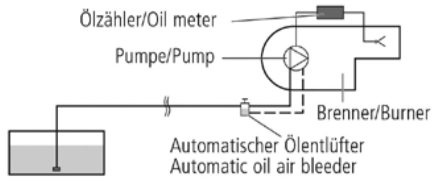
2.Building in the oil meter on the suction side, a filter has to be installed in front of the oil meter with a mesh size of 50-75 μ.
Air inclusions have to be avoided since they cause measuring errors. If necessary the pipeline system or the screwed connections should be checked for tightness.
3. Switch off heating plant and remove burner hood if necessary.
The measuring unit can be fitted under or outside the burner hood.
4. Adapt the pipeline as appropriated.
The measuring unit must be easily accessible.
- Clean any swarf and other contamination from the lines.
5. Attach retaining plate [5].
- To ensure correct venting during commissioning, the oil meter can be mounted with the connections (A+E) facing downwards or backwards. Attention! The oil meter must not be installed vertical standing. Ensure that the counter wheels are easily visible.
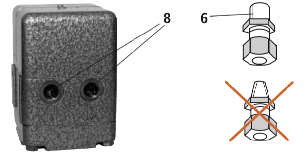
6. Remove sealing plugs [8] from the back of the oil meter and screw in screwed plugs [6] with cylindrical threads.
- Do not mix up the inlet and outlet.
- A professional and tight pipe connection is achieved using the supplied aluminium sealing rings [2]. Hemp or sealing tape is unnecessary.
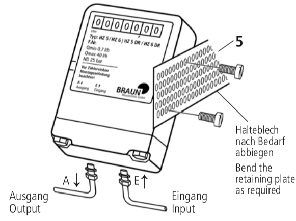
7. Attach oil meter [1] to the retaining plate [5] using the fixing screws and washers.
8. Connect pipes and tighten up the screwed connections.
Safety Instructions:

Before mounting the oil meter these instructions must be carefully read through and followed!

Danger of fire from combustible liquids! Take great care during grinding, cutting and welding work!

Fires, open lights and smoking are forbidden! Always keep fire extinguisher ready for use!

Danger of injury from sharp edges! Be careful during mounting!
Starting up
- If the oil meter is installed in the pressure pipe before the burner nozzle, on the discharge side, the pressure in the closed pumps should be temporarily reduced before the appliance is operated, in order to prevent damage to the oil meter’s membrane caused by pressure surges.
1. Switch on pump.
2. Slowly open shut-off valve.
- Avoid pressure surges so as not to damage the measuring unit!
- Entrapped air causes false measured results and can lead to damage!
Recommendation
When installing the oil meter in the pressure line in front of the burner nozzle.
In order to prevent the possible occurrence of subsequent dripping, we recommend the installation of an additional solenoid valve after the meter.
Maintenance
- Regularly clean the prefixed filter
- Check connections and lines for leaks
The measuring unit must be kept clean but requires no maintenance.
After 8-10 years, we recommend a factory inspection of the oil meter to ensure its measuring accuracy.
Example 1
Connection to the active port e.g.: Battery gauge
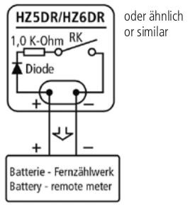
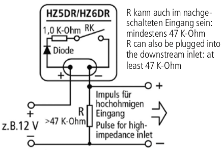
Example 2
Connection to the passive port
Technical Data
|
Durchflussbereich HZ 5 DR Brennerleistung |
0,7 … 40 l/h (0,6 … 34 kg/h) 7 kW … 400 kW |
|---|---|
Durchflussbereich HZ 6 DR Brennerleistung |
1 … 60 l/h (0,8 … 50,4 kg/h) 10 kW … 600 kW |
Ablesemöglichkeit am Ölzähler |
0,01 l … 99999,98 l |
Messgenauigkeit |
±1 % |
Nenndruck |
25 bar |
Druckverlust (Besonders bei Einbau in der Saugleitung zu beachten!) |
0,05 bar … 0,2 bar |
Heizölsorte |
EL according to DIN 51603 |
Temperaturbereich/ Umgebungstemperatur |
–5°C … +70°C |
Anschlussgewinde |
DIN 3852-X-G 1/8″ internal |
Maße |
60 x 60 x 85 mm |
Gewicht |
0,6 kg |
Pules Output
- Connection via screw-clamp terminals
- Reed contact: max. 30 VDC,
Imax = 6 mA, Rs = 1.0 K-Ohm/0.6W (observe polarity) - Principle: The power circuit of a counter or other registering device attached to the plus and minus terminal clamps is closed via the reed contact and 1.0 K-Ohm impedance. The input impedance should be at least 50 K-Ohm to ensure that the additional counter reaches its switching threshold.
- Pulse value:
- 1 pulse = 0,02l
- 50 pulses = 1l
- Max. frequency at 60l/h approx. 1Hz (Due to the reed contact [-deboun- cing-], use remote counter with dampened input)
LCD Counter
- 6-digit with 0.1 l display resolution
- 3V/950 mAh lithium-ion battery
- Lasts at least 9 years (depending on temperature and moisture)
Ambient temperature / atmospheric moisture - 0 to 60 degrees Celsius
- Max. 85% RH, non-condensing CE-compliant electromagnetic compatibility
- DIN EN 61326-1 2006-10 version
Ambient Temperature / Humidity
- 0 to 60 degrees Celcius
- Max. 85% RH, non-condensing
Electromagnetic compatibility CE compliant - DIN EN 61326-1 edition 2006-10
Installation Options
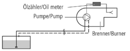
Two-pipe system – installation in pressure line
One-pipe system – installation in suction line
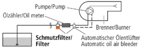
One-pipe system – installation in pressure line